Control Panel Wire-Up

Was on a roll today but the soldering iron tip is pooched, bummer.

The batteries would not fit without modifications to some of the switching, so it was handy that I decided to forgo the continuity / proximity cue circuit, and turn the speaker terminals into a charging input. The batteries are oriented in a manner that won't interfere with switches and will allow the panel to close. The preference would have been a symmetrical layout to keep the weight distributed, but I consider myself a bit lucky to have been able to fit them within the unit.


The cells are traced out. X marks are made at six points half way along the edges, holes wide enough to accept large zip ties are drilled at these points.


Batteries are tied down tightly with zip ties. In a worst-case scenario the zip ties can always be cut for removal, and replaced for return of the cells.


Everything seems to fit.


The batteries are wired in series (positive pole of one battery to negative of the other) to double the voltage to 12. For an added measure of protection, I decide to add a fuse to the circuit. Holes are drilled into the side wall.


Butt connectors are tied together and connected to the lead coming off the positive terminal of the cell pack. Zip tie is pre-pulled.


This is designed to protect the circuitry (and battery) from a dead short, so a 10-ampere fuse should be low enough to protect, yet high enough to allow active current through. I would have preferred a breaker, but they are about 10 bucks, and this solution was less than a twentieth of that.


Wiring is started. The circuit is simple enough that no bread board or PCB is required, but after a 5 minute brainstorm on how to turn a schematic into reality, a wiring harness is sketched out. From the sketch comes a working model.

It is amazing how thought-out plans get dumbed-down when being executed; upon building the wiring harness I see how moronic it is to have four diodes wired parallel when one would to the trick.


All connections made with butt connectors and ring terminals are done. Since there's no access to a working solder iron at this time, some planned steps are skipped, such as the connection of LEDs. These steps will be returned to.


Looks a bit of a mess, but traces out ok using power supply / multimeter.

Time to test:


Control Panel Prep

Between the local electronic parts store, Princess Auto and my garage, most of the parts necessary are at hand. The furnace efficiency meter is gutted completely, parts are recycled where possible. A five-position switch that was part of this unit, will be re-used as the set selection switch on the new panel. Bonus, these are not cheap switches.


A battery I've had kicking around for a while is depleted. While it charges, the old efficiency meter faceplate is scored to remove all decals.


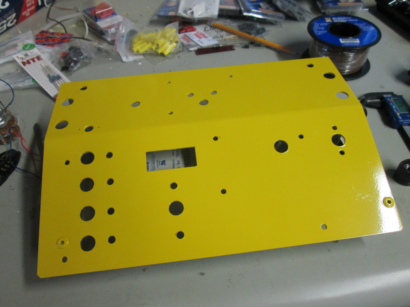
Can't do anything about the holes in the faceplate, can only accept them. So the switches are plotted out while being mindful of re-using existing holes. New holes needed are marked in pencil.


Holes are cut according to the diameter of the switches that will occupy them. The faceplate is soft aluminum and easily cut with a step bit.


LEDs and switches are clearly marked on the inside of the faceplate.


Black, beige, baby blue and yellow spray paint is available on the shelf. This is a no-brainer, I think. The faceplate is painted outdoors and left to cure.

If I was forced to watch Tremclad dry, I would starve to death. The painted faceplate takes three days, and even then is very easily marked. Maybe I'm just not patient enough.


Switches are dry-installed, along with LEDs. Some unused holes are filled with dummy screws, which at least look like they serve a purpose, unlike holes. The layout would be different if the faceplate was blank, the speaker terminal being in the very center seems dumb. At this point I second guess the whole 'continuity / single cue' circuit. This may end up changing.

At least the four cue-firing momentary switches on the lower left make sense, and the 5-position switch above it will be intuitive.


The battery I planned to use is completely dead. I attempt to revive it but no success (multiple YouTube videos explain this process). D-cells could work out, though I'm averse to disposable batteries, and their round shape means more work to mount. So the budget is blown by $24, and two six-volt, 4.5Ah rechargeable cells are sourced. I choose two 6 volt instead of 1 12 volt as the goal is to squeeze the power source inside the Schwartzvolcker panel, 6 volt cells are half the size making the volumetric puzzle easier to solve.

At this point, given the weird layout, unnecessary (and second-guessed) continuity/single cue circuit, and the need to charge the batteries that may be contained within the panel, I think of changing the purpose of this circuit's switch (to ON/CHARGE), and speaker terminal (to accept a charge from an external source). More on this later I'm sure.

A nice feature of the old furnace efficiency meter was the flip-up action of the faceplate. This will make it easier to work on and service in future.


Next steps are figuring out the battery orientation and wiring the whole thing up (mostly) per the plan. Attention will then be turned to the junction box and cue slats.

The Schwartzvolcker Conception

The firing system is planned starting backwards from the point of e-match ignition. Known factors include:
  • Anticipated 75-100' distance from control unit to ground zero.
  • 12v circuit preferred due to readily available parts & battery.
  • 350mA+ current to ignite e-matches.
  • E-matches are 6' in length.
  • Ground zero will have a radius of about 8'.
  • Keep costs to a minimum.
The final point is important. My budget will be around $60, tops. So looking around the garage, I have some switches, resistors and LEDs that can be used. I have access to a large amount of scrap CAT5e cable which can also be incorporated. 18, even 20 gauge wire costs $0.10 to $0.15/ft; running up to 20 cues could potentially mean a half-mile of wire costing upwards of $375. The CAT5 is 8 individual 24ga wires. Over a potential 200' run, this could present a mild risk of melting when a larger amount of current is applied. It is best to be safe, so the plan is to double up into pairs, and cut the resistance in half.

I start out with a few hand sketches of the planned circuitry, again working backwards with the known factors. The easy thing about planning DC circuits it to follow the directional path of power in a complete loop - provided the function of each device in the circuit is understood. I finally get a rough draft of what I think will work after reading a few highly educational posts on this subject by "JoeRatman" at PyroUniverse (Thanks Joe). Among them, the use of cheap speaker terminals to easily field-wire e-matches to cue slats, the part numbers of some diodes necessary in the circuit, and how handy it is to have a lower current circuit run beneath the firing current to visually display continuity (and therefore readiness) of each e-match prior to ignition.

Final draft sketched.
The idea of a junction box of sorts is introduced; this will decrease the amount of cable needed by about 75%. In theory, the control unit will be in the lap of the operator, with two CAT5 cables leading 75-100' away to the junction box. The junction box will split the signal to five separate cue slats, themselves up to 20' away from the junction box. From the cue slats will go the e-matches - up to six feet away. 

There will now be seven separate parts to the system - Control unit, junction box and five cue slats (sets) each with four pairs of clip-downs for e-matches. A rotatory switch will be used on the ground return wire to toggle between the sets. Four additional cues are added in parallel to the last set (E) since it is closer to the finale in the show, when there are often at least two items being ignited at a time.

Each part of the system is planned to be easy to set up and dismantle. Ideally, cables can be pulled out and wrapped up for next use. To keep costs down I plan to hard-wire the CAT5 into each set, though their connections into the junction box will be removable.

The sketch detail, along with notes made after reviewing several times, is entered into MS Visio. This program is meant for flow charting, but has a library of electrical symbols that are handy to draw circuits. At this point some calculations are made to determine the resistor values needed to run the continuity circuit, and proper location of diodes. A single cue, test circuit is also added, to facilitate e-match testing without setting up the junction box or set slats, and perhaps to ignite a close-by fountain or wheel.


When it comes time to save the file, I name it 'Schwartzvolcker'. Really, for no other reason than it sounds bad-ass German, invoking feelings of sturdy, robust engineering...

A dead 'furnace efficiency meter' is chosen to be the base for the Schwartzvolcker. It comes in a small latched case, and the face swings open for access to the inner workings. Not sure the battery will fit into the unit, however.


Now everything is on paper. Using the completed drawing, a parts list is created. The next step will be sourcing parts and starting the build.

An Inexact Science?

Touched upon in a previous post was the fact there's no exact science to the show (as previously planned), which in hindsight was bothersome. There isn't the level of quality control at the manufacturing level to ensure it, nor the tools commonly available to the consumer to mitigate it. Plastic bases are glued to mortars at off angles, fireworks occasionally come with missing fuses or are complete duds, internal timing of items is plus/minus many seconds, and there is sometimes the odd effect that gets shot out at a wonky angle or a weak misfire. Such is the way with consumer level fireworks, larger margins of error must be acceptable I guess. Only stating this since past posts have been quite specific; perhaps instead of trying to reduce the callow nature of what was being dealt with (in comparison), I'll just conquer it. Alas, I love to learn.

Chinese quality controls are not like Canidian ones.
Adjusting angles on homemade racks and cutting visco runs accurately to ensure desired timing between effects may or may not yield the planned result, so with the proposed electronic ignition I'll try to get as close as possible. This is a sea-change of sorts with the whole plan, but it will be adapted.

Beyond building an ignition system lies the gateway to pro pyro territory. So it makes sense to go as far as possible not only within my knowledge level and skillset, but within legal limits. I'll attempt everything I can that is available to any free adult citizen of Canada (barring local bylaws).

I think it would be fascinating to learn to make my own pyrotechnics, but federal law requires some significant licensing, which is understandable considering the necessary knowledge and the risks involved. Maybe some day. Perhaps before then I'll have the budget to invest in a much larger, music timed extravaganza. Such an effort would require a large swath of private property outside the city, a 50+ cue RF ignition system, miles of wire, a PA setup, many hours of practice and preparation, and three thousand-odd fireworks.

Given I can think of a couple better ways to spend twenty five grand, I don't see this happening any time soon. Here is an excellent example of someone who did though, using only consumer fireworks and some serious skill. I have tremendous respect for the work involved in preparing and executing such a show. Awesome!

More Thoughts on Electronic Ignition

Since the last post I have spent some hours thinking about electronic ignition, at times to the point of preoccupation. I'm drawn to the idea of having far greater control over the show by timing key elements of it, particularly the finale. I must admit, prior to pulling out the Predator (a generous gift given to me) for some testing, I hadn't really considered how electronic timing really is natural evolutionary progress for the amateur pyro. I revisited the overall plan for this year's show, it has double the complexity of last year's. In essence, relying on visco and expecting perfection will mean much good luck. It is time to bring precision into the mix.

I'll introduce another hobby of mine; electronics. The Predator is a good device for the yearly casual 'family-pack' buyer; the system provides safety and one-at-a-time accuracy. Unfortunately the time needed to change ignition clips can't be tolerated in my show. I'll skip right over the Predator and move into custom territory.

The Predator is a five cue, single 'slat' system. This means the system will fire five times before a break is needed to reload the power source with a bank (slat) of fresh e-matches. For an hour or two this seemed like a good idea to me, the last post even finished by stating the three acts would be broken into five. But five acts (cues) still means up to 25 items in a row ignited by many visco connections, this may still be too many. Sure, great care will be taken to be precise with the fusing, but why not try to be better by removing the variables that come with visco?

I started out by having a closer look at the Predator system to see whether it could be hacked in some way. It was quickly determined that a number of inadequacies exist that would not make it worth the effort (no simultaneous cue firing, small arming area, underpowered at 3 x AA batteries). It's just too consumer-grade to be able to troubleshoot in the field if something goes wrong ("Hey Al, change the batteries!"). However the e-matches that come with it are available commercially for around $0.75 each, and will come in handy.

So what makes the Predator work? Electrical current. When the receiver (that contains the larger power source) is provided with the right signal from the transmitter, it closes a cue circuit and provides electrical current to the e-match. The e-match is at the end of two thin yellow wires, one positive, one ground. The tip of the e-match is a small chip with wire that is even smaller gauge than the yellow stuff that feeds it, and it is doped with a small amount of combustible material, usually KNO3 (potassium nitrate, or gunpowder). This thin alloy on the chip melts due to the current passed through it, which burns the KNO3, and the fuse attached to the clip. Ignition.

Having put the Predator away for now, I'll get to work on some designs. Reviewing the original order of the show, and the number of 'splits' of visco necessary gives me the opinion that a 20-cue system will fit the bill. The parts necessary are relatively cheap, but the budget will be maintained since what is being built can be kept for years - invoking an out clause in the $1k rule I tried to abide by since the start of this project.

Before starting the designs some basics are checked out. Like what amount of current ignites the e-matches being employed. See for yourself:


332mA was the final reading before burn.

Finding this amount is key to building circuitry that operates below it, such as a test circuit to make sure e-matches are problem free before ignition, without igniting fuses. 50-100mA should be safe, less if it will run the circuit (depends on number of devices in it). That threshold will also have some bearing on what voltage the power supply is - the test setup was 5V - but this will depend on resistance in the circuit (length of wire, resistors, etc). To be determined. If I use a 12 volt battery Ohm's law says the current demand to ignite would go up to 800mA.

I'll also need to give some thought to the device itself; layout, ergonomics and what makes sense. There seems to be a few places on line with some ideas. It would be preferable to use stuff I have kicking around as well, perhaps the final product will look like something out of the original Star Trek series...

Also to be determined.

Electronic Ignition


The plan is to use the Mystical 'Predator' firing system to start each act in the show, and it is time to test it out. While this item seems idiot-proof given there is only green and red buttons on the transmitter, and a single on/off button on the receiver, my first test doesn't go so well. The instructions are easy to follow, but I don't get the desired result.


After several attempts, I refer to the "replace battery" section of the instruction guide, and decide it is probably wise to replace the junky looking, lightweight "Raymax" batteries and the little watch battery, even though the LEDs lit up as they were supposed to. As with most portable powered items made in China, the included batteries leave much desired.

The purpose of this kit is to pre-wire up to five fireworks / sets, or 'cues', and be able to retreat to seated comfort a distance away and remotely ignite the cues at the press of a button. On this device, the green button provides instant ignition (in numbered order on each e-match), while the red resets the whole program.

I'm using one inch strips of visco as the test subjects attached to the e-matches, since fireworks ignition runs against local bylaws today.


In the second attempt, there is some progress; though no visco ignites. I see light inside each e-match during every subsequent press of the button, which is more encouraging than take 1. Furthermore, the LED inside the transmitter stays on for a couple of seconds instead of a flash.

Closer inspection of each clip reveals some signs of combustion inside, but the lack of visco ignition is troubling.


For the third try - and using my second set of 5-gang e-matches - I tie in alternating quick-fuse and regular visco, thinking there might be a difference. At this point I discover that the e-match clips snap in when depressed with some force.

Take three worked out well. Didn't matter whether the visco was quick or regular, the problem was definitely with the locking clip position. I wish this was mentioned in the instructions, wouldn't have wasted a whole bank of e-matches. However, success is here so overall I'm pleased.


The plan for the show is to have three acts, though I'm now thinking the more it is divided, the greater the insurance policy that the show will go as planned. Five cues making five acts may be the better way to go.


Preparing Racks, Part II

A welcome drive-by sight last week, was running low on scrap wood.
Rack prep continues, though I'm well ahead of schedule with just over a month left until the show. The focus is now primarily on items that need support or their own rack assembly as opposed to being mounted directly to a pallet. Items that require this are typically fastened / secured in one way or another to a piece of wood that will in turn be fastened to the pallet prior to wiring all events up.

There are multiple ways of doing this, examples of which are pictured.
 
Depending on the effect, and at what point in the show it will ignite (and whether it will run in tandem with one, two or more other effects), spacing and angles must be considered. Spacing for the visco run, and angles depending on what the effect is. Most of the items being fired simultaneously are fanned to occupy as much sky space as possible.

If the plan is to have true simultaneous fire, the racks are wired up with visco, wrapped in tinfoil and stored for now. In some cases, some delay is desired so mixing visco speeds is needed - an endeavour I will undertake in the near future.

* * *

Six mines were mounted on angle scraps to a 2 x 8 chunk, which was attached to a small 12-shot Sky Rocket with Report rack.


36-shot fanned Air Bomb rack was built by pre-drilling cavities and pressure fitting the tubes (see the Rocket Attack post).


An 8-shot "Shotgun Shell" rack. Drilled right through this time, interestingly the plastic bases mimic real life shells in that the very bottom diameter is larger than the bore, which helped here. Glued the bases with PL before placing the charges back in & wiring.


Twenty four Mini Air Bombs. Didn't opt to fan this rack since the desired effect is strictly for the noise, and a separate wide angle event is planned for the same time slot in the show.


Two angled Angel Wings barrage tubes fastened to a vertical plank with zip-ties. The plan is to fasten the plank with screws through the underside of the pallet. 


More zip-tie action; seven Asteroids tubes angled 10 degrees apart, this rack will be fastened to two vertical posts sticking up through the pallet stringers, each tube's base will be touching the pallet to ensure none escape from blow-back.


Rocket Attack

Today we're building a small rack for multiple (sixty) mini single-shot mortars called "Sky Rocket With Report". A moment after ignition this item answers with a small caliber pop at mid-height (50-60'). They cost twenty cents each. On its' own, it is not very exciting. But based on last year's experiment, multiples all at once can provide an interesting interlude between longer lasting effects.

Once again the item diameter is measured. 0.41 is about 7/16.


Wanting to allow reasonable space between each tube to run the visco (½"), and depending on the config (4 x 15, 5 x 12, 6 x 10, etc) a corresponding-sized block of wood is required. Even numbers are more desirable to make the visco run economical - i.e. one visco fuse delivering ignition to two items at once, instead of one. I decide on 6 x 10, and find a block that is 7" by 15" in the scrap heap. Equidistant intervals are then marked (in this case every 13/16").


A grid is drawn lining up with the 13/16" marks. Given the 6 x 10 layout, it is decided that the length will face the audience, and the effect will be fanned perpendicular as a result. Mounting angles will be 2, 7, 12, 17 and 22 degrees in both directions. These angles are marked on the grid lines.


The drill press plate is angled to accommodate the desired angles. The drill press has a built-in angle gauge but it is not very fine, an angle finder is used for tuning.


Holes are drilled, stopping short of going through the block using the limiter on the drill press. The block is turned around to drill the same angle in the other direction.


All sixty holes are drilled on the grid, at the desired angles. The act/sequence number is written on the rack to ensure proper firing order in the show.


"Sky Rocket with Report" is unpacked. The plastic points used to help submerge the tube in soil (and make the 'live' end more obvious to the user) are removed easily.


Quick fuse visco is cut to estimated length needed. Zip ties are pre-pulled to make fastening easier. The first two tubes are inserted into the drilled cavities and fastened, starting a pattern that will continue until completion - each tube's ignition fuse running in the same direction as the linking visco. This provides greater contact in the off chance a portion of either fuse does not spit fire / ignite.

Drilling the holes the same size as the diameter of the tubes makes for a perfect pressure fit, avoiding the need for any adhesive use.


Zip ties are hung on the length of visco to make the process more efficient.


The Sky Rocket's green fuse is long, and this will be used to our advantage; when attaching each pair of tubes, the previous two are included in the zip-tie bundle virtually guaranteeing ignition.


After each row is complete, the surplus pulls are cut from the zip ties.


The efficiency of the visco run can be seen running in an "S" pattern, with two tubes served per pass.


The rack is complete and can be considered armed.


Prior to putting this away, it is wrapped in tinfoil and taped up, making it reminiscent of a shiny store bought cake. This is simply for safety, much like a tape fuse covering found on any consumer firework.

The plan is to repeat this process with racks of 60 Air Bombs, 36 mini Air Bombs and 12 more Sky Rockets for other parts of the show.

Proto wheel #2 was tested to mixed results. Not sure I'll bother with a third.


Hard to conclude whether the problem is lack of thrust, too much resistance in the whole axle mechanism or a combination of both. When it was spinning it performed very well, and offers a great alternative to wheels that cost the same or more. Just seems that the quantity of work required to make sure the thing spins flawless is a little too much. I could probably figure it out, but I've now burnt up 8 Carmel Fountains, and may need another 12 before perfecting it.

Trying Fountain Wheel Again

If at first you don't succeed, try again.

The cardboard supporting 'proto wheel' had to be extinguished with water.

Having looked at 'proto wheel' a little closer I think it got hung up on the mounting post. A new wheel was fashioned, though this time paying much closer attention to the mounting and ensuring it spins freely.


Proto wheel #2; narrow cardboard strips instead of a full card backing.
Far greater gap between post & wheel, no zip tie knuckles to get in the way.


Testing this evening after sun down.