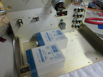
The batteries would not fit without modifications to some of the switching, so it was handy that I decided to forgo the continuity / proximity cue circuit, and turn the speaker terminals into a charging input. The batteries are oriented in a manner that won't interfere with switches and will allow the panel to close. The preference would have been a symmetrical layout to keep the weight distributed, but I consider myself a bit lucky to have been able to fit them within the unit.
The cells are traced out. X marks are made at six points half way along the edges, holes wide enough to accept large zip ties are drilled at these points.
Batteries are tied down tightly with zip ties. In a worst-case scenario the zip ties can always be cut for removal, and replaced for return of the cells.
Everything seems to fit.
The batteries are wired in series (positive pole of one battery to negative of the other) to double the voltage to 12. For an added measure of protection, I decide to add a fuse to the circuit. Holes are drilled into the side wall.
Butt connectors are tied together and connected to the lead coming off the positive terminal of the cell pack. Zip tie is pre-pulled.
This is designed to protect the circuitry (and battery) from a dead short, so a 10-ampere fuse should be low enough to protect, yet high enough to allow active current through. I would have preferred a breaker, but they are about 10 bucks, and this solution was less than a twentieth of that.
Wiring is started. The circuit is simple enough that no bread board or PCB is required, but after a 5 minute brainstorm on how to turn a schematic into reality, a wiring harness is sketched out. From the sketch comes a working model.
It is amazing how thought-out plans get dumbed-down when being executed; upon building the wiring harness I see how moronic it is to have four diodes wired parallel when one would to the trick.
All connections made with butt connectors and ring terminals are done. Since there's no access to a working solder iron at this time, some planned steps are skipped, such as the connection of LEDs. These steps will be returned to.
Looks a bit of a mess, but traces out ok using power supply / multimeter.
Time to test:


No comments:
Post a Comment