Apparently the weather might suck:


So a 30% chance of rain is a 30% chance the show will be bumped? I guess if one were betting, this opinion would be analyzed. It states 'showers', which by the definition I understand are those 5-15 minute precipitating cloud banks that pass occasionally on an otherwise hot sunny day. So a 30% chance that showers will appear SOMETIME during Sunday is actually pretty good odds we will be dry between 9:45 and 10:15PM, right? Is this correct?

Then why the stinking, grey-cloud rain graphic? Why does the human race tolerate weather forecasting when we get so pissed off about a bus that's 5 minutes late?

On this here eve-eve I'm a little anxious that I may have forgotten something, particularly since I already discovered a few things tonight that I forgot. It was a bit of a mind bender plotting all the items, an inventory of sorts, then comparing to the plan and seeing that some predetermined cue points didn't really add up. There were also a few little racks that didn't get built, and the sheer volume of fireworks that need to be visco-wired is a little whelming. No rest...

All racks are loaded.
My great friend Paul will assist me on Sunday. This is essential for a number of reasons. The most important, to double-check each others' work. There isn't a large amount of skill in what's being done here, but visco wiring is a monotonous task that is time consuming, these two ingredients are key to glitch cocktail. A second set of eyes attached to an interested brain is most welcome.

Some of these racks are two-man lift, and at ground zero it is nice to have another opinion on variables such as rack orientation, wind direction, starting time, crowd control, troubleshooting, etc. There seems to be so much I have to keep in my head (paper will go only so far during the show), it is relieving to have a trusted resource to bounce these things off.

*  *  *

Finished loading all racks tonight. there are a few that remain, these will be adhered after fusing and are typically doubled-up items that share a single fuse. All that needs to be completed is the 60-shot Air Bomb rack and a 12-shot Sky Rocket rack.


Discovered a funny thing about Menace, a cake I've used a few times before. It has a minor case of the need-to-appear-more badass-itis. I really don't get it.

It's only 25 shots, so why 36 tubes?
Seeing everything together gives me a good idea of how large ground zero will be. Given there are two slats that have over 20' available from the junction box (the other three are 12-15'), I'm wondering how far apart the racks should be spaced. Not sure it will really make a difference. Perhaps Paul will have an opinion on this.

No worries, BBQ tank is empty.
Multi-speed, visco length vs time calculating sheet.
We have to prepare for nine guests at our house and a party as well, so tomorrow will be spent largely away from this project though there seems to be things that need doing. Sunday is reserved for this.

Tomorrow is still special though, in that the bylaw says it's ok to blow off fireworks. In the evening we'll do just that, with a full-on test of the ignition system.

Pluggin' Away

The show order is final. The spreadsheet containing the original plan was modified (adding in the impluse-buy extras) and extended by two columns. One column contains the amount of time between electronic ignition and the remaining items in that cue (to determine type, cut length and install of visco fuses), and the other with operator instructions, such as "20 seconds after start of Rainbow Candles".

Looking ahead to the live show, I'll have to pay close attention to what events are occurring to make sure I stay within plan. Though I have some memory of individual items based on past experience and/or watching them on YouTube during the planning phases, the key will be noting when they start and end. Worst case scenario (operator distraction, visco failure) is a couple of seconds pass without any action - and the very next cue is ignited with the press of a button. Duds, whether firework or e-match, are worrisome. If an e-match is bad there will be a delay while the cue is manually ignited. It may be skipped over depending on what it is. A dud firework is almost worse. If a solo, there may be up to 30 seconds of silence while the visco continues to amble its' way to the next item. Worse still would be a dud firework at the start of a cue; it may be difficult to tell whether the fault lie with the e-match or the firework without cautiously approaching ground zero for a look.

No real sense in worrying about this, I have to remind myself that this show format is essentially a first time effort.

The stats in the plan are interesting; there are 80 different events (not counting multiples) containing 437 items, with 3,038 individual shots. 264 of these items are either air bombs or candles. There will be no more than a 2-3 second break over a seventeen minute and fifteen second show. We shall see how close this is kept to.

The weather forecast continues to be positive, with little change from yesterday's. I'm pleased that Sunday is no longer book-ended by a potentially rainy Saturday and Monday.

*  *  *

Cake racks are prepared using a simple method. Bottoms are removed on each, and they are glued with PL (construction adhesive) in the marked out areas on each pallet rack. I had previously drilled holes where visco will run to each fuse from the cavity below the pallet deck. The paper wrap at the bottom of a cake is typically flimsy and will not hold a cake to the surface in the event it is knocked. Adhesion directly to the inner tubes is required. PL will glue almost anything to almost anything.


A couple of racks have all items mounted. In some cases a items can't be glued down, it would restrict access to the fuses. Adhesion will be completed at time of visco connection.


Wedge shaped shims are utilized to angle some mortars. these are fastened to the rack deck with screws.


Some housekeeping will be in order tomorrow; the workshop is trashed. I'll need some room for the racks, after they are mounted there's no tipping them onto their side to save room. Tomorrow I will check if I can obtain a trailer as well. I don't think all these would fit in the truck.

Forecasting Awesome

I typically ignore 7-day weather forecasts since they are like rolling dice. Starting to pay attention today though, and Sunday looks perfect:


Added a couple of items into the program (since the budget is blown anyway), spending another $37 on a few effects to augment the finale, and a special fountain to kick off the show.

Planning is now underway to determine what items are best to attach directly to ignition cues. There are twenty to use, but at least five should be reserved for the finale. Obviously distance between items has considerable bearing on this, it makes little sense to connect racks using visco, rather connect items within racks. Individual multiples being fired at once are going to be considered as well. I don't want to connect much more than eight effects with the slow burn visco to avoid any timing issues. Once this plan is determined, it will be used to wire up the visco on blasting day, and provide me with a firing menu that can be referenced during the show.

I've made some minor modifications to the overall order, but generally sticking to the initial plan. The show will kick off with some ground effects, then launch into a steady feed of individual effects for several minutes, interspersed with smatterings of air bombs, mines and mortars. Cakes with some of the best multi-effects will occupy the middle of the show before racks are ignited that run in tandem with each other. About two thirds the way in, mines and fountains will join the show for multiple heights of effects. Nearer the finale, up to six different items may be in the midst of firing at once.

Rack mounting work will begin shortly after the ignition plan is finalized this evening.

T Minus 6 Days

The heat is on. Focus must now be spread among a number of items on the to-do list, particularly anything needing testing / verification.

All bugs are worked out of the ignition panel. Instead of spending hours trying to figure out how the CAT5 dual receptacles mangle the electrical signals, they are yanked out and disposed of unceremoniously. Taking a closer look, the two jacks are tied in together on the internal PCB. Surprised I didn't see smoke in hindsight...


The jack is replaced with E-Z snap receptacles in both the jx box and the ignition panel. This has added $26 to the cost, almost doubling the original $60 budget, not to mention the painful waste of time.

The 20 speaker terminals ordered in were picked up yesterday afternoon; the salesperson asked "are they for fireworks". Interesting that others in the area not only build stuff like this, but obtain parts from the same supplier!

Attention is turned to creating the cue set slats, so more scrap wood is needed. 4 x 4 blocks will do the trick since they are reasonably heavy and will stand up to some mild abuse in the field. Five are cut to ~8" lengths.


Channels are routed out almost the full length of one side of each block. The channels will contain the cabling.


Diodes are soldered to the negative lead of each speaker jack. In a DC circuit diodes allow power to travel only one way (in the direction of the marking). In this case they will ensure the LEDs go out after each cue ignites, and better yet prevent leakage current from accidentally igniting other cues.


Each speaker terminal is installed in ascending order, keeping with the colour protocol on the RJ45 cable leading to the positive, and tying in to each diode with a single wire on the negative side.


Time to test when the first cue set slat is complete.


Testing goes well enough that four more slats will be built the same as the first, and the system will be ready for a full, 20-cue live field test this coming Saturday. I could not find the Predator e-clips at the local fireworks retail trailer, but they had Launch Kontrol ones that look very similar at the same price. These seem to work just as well.

The whole kit, minus four more 4-cue slats that must be made.
The final schematic, showing the changes in build drifting from original plan.
Apart from the upcoming field test, this will be all posting about the Schwartzvolcker before the big show. Barring some catastrophe, it will be charged up and ready to deliver a zap to the place I want when I want!

Tomorrow we'll turn our attention to loading up pallet racks and securing items prior to wiring.

Troubleshooting


A bench test with the entire system wired up, but testing individual cues, revealed a strange condition; on all five slats the first two cue LEDs were lit when either the orange pair or blue pair were connected (cues 1 or 2). Keeping in mind the following protocol:

Orange / orange-white pair = cue #1
Blue / blue-white pair = cue #2
Green / green-white pair = cue #3
Brown / brown-white pair = cue #4

This pattern was found at the output of the jx box. Testing at the output of the panel is even stranger, with LEDs 2 and 3 lit when the orange or blue pair is sampled individually. Again, green and brown (cues 3 and 4) remain in fine working order.


The panel is opened up, and the entire internal wiring build is compared closely with the schematic plan. Everything seems to match perfectly. The same test as above conducted at the internal wiring level (before the CAT5 receptacle) and it performs without flaw. The CAT5 box is problematic!

The receptacle is tested for continuity in two places: the strip where the RJ45 is punched, and the tines that make contact with the cable crimp connector. This test yields an interesting result, that the punched strip, labeled 1 through 8, does not correspond with the tines. More like:

Strip positions: 1 - 2 - 3 - 4 - 5 - 6 - 7 - 8

which are cues: 1 - 1 - 2 - 2 - 3 - 3 - 4 - 4

coloured: O - Ow - Bl - Blw - G - Gw - Br - Brw

get moved to: 4 - 4 - 2 - 1 - 1 - 2 - 3 - 3

within the receptacle.

Assumed problem is sketched out, red ink indicates likely issue.
This seems to explain why orange and blue are affected. At some point, probably within the receptacle punching or cables that were crimped up, the blue/white and orange/white are crossed over between positions three and six. Thinking that each cue pair is simply doubled up for a halving of resistance, I need not pay fine attention to the pairing position! For example, orange and orange/white may have originated in positions 1 and 2 respectively, but terminated in positions 2 and 1 respectively, which would create a closed circuit for two cues due to the receptacle mixing up the pairing.

This theory is also supported by the condition found directly in the output of the ignition panel. By using the same receptacles on both transmit and receive sides, they should cancel each other out if the cables and punch strips are pinned out paying attention to the pattern with each pair.

The problem is with the cable as the testing seemed to indicate.  Pins 3 (blue) and 4 (blue/white) are reversed on one end. The end is snipped off, and re-crimped correctly.

One of these cables is not like the other...

The time consumption of this troubleshooting is costly, but I'm no data cable whiz, so as annoying as it is, it's still a learning experience.

Control Panel Nearly Done

The Schwartzvolcker project is nearly complete. All that remains are the five set slats that require backordered parts, among minor tweaks. Fingers crossed.

All bare connections in the control panel are soldered up, all screws tightened and all M/F joints are squeezed. Also replaced the sketchy home-made ATO fuse holder with a $3 automotive unit for peace of mind. The unit is sealed with screws, and lifted & shaken before the overall circuitry is tested. Test consists of continuity / LEDs lighting up when circuits closed (and off when open) on all four cues over all five sets, and 'ignite' (current spike) for all twenty combinations as well. Additionally, the charging circuit is tested, but not before adding a diode facing toward the battery (so current can NEVER flow to the speaker terminals on the panel). Everything bench-tests positively.


A plank of 1 x 8 is cut to about 14". Using a jigsaw, a hole is cut to allow an old dual CAT5 receptacle to be flush mounted.


The jx box is attached to the reverse side of the plank. 2 holes are drilled through the back of the box to line up with the receptacle. 12" pieces of RJ45 cable are pulled through and stripped to 3", inside the dual CAT5 receptacle. Each of the 16 individual wires are punched into their proper locations.

On the flip side, one of the RJ45 cables is stripped and attached to the 'positive' (cue ignite) posts according to colour protocol (previously decided as orange=1, blue=2, green=3, brown=4). The other cable is pulled through four 3/16" holes drilled into the jx box the the bottom right.


A mild annoyance with the project is that it would have been much easier if it were a 4x4 (16 cue) system; there are four pairs of wire in RJ45, and it seems most of my available accessories are tailored to it. Alas 16 cues is too few.

The four coloured pairs are connected to one side of a four-post electrical strip connector. The strip is then bolted to the jx box. These connections will be negative ground (set) wires, each individually returning power from whatever slat is selected in the five-position panel switch. They are labelled according to their set position. The CAT5 female receptacles do not need labeling since the positive power is supplied in four pairs controlled by the ignite switches - doesn't matter where they are plugged in. That said, it is critical the negative return wires are connected to the correct strip post!


The jx box is completely wired up and ready to close. Note the hole drilled beside the strip connector - Must make room for the fifth set's negative return wire, that will be run to the control unit (since there are only four pairs in RJ45).


Two additional planks are nailed in to the double sided junction, shown here in a field check. Cosmetics / finishing will occur shortly now that testing was positive. The plan is to cover it with another piece of wood to protect if from ground zero fallout and (God forbid) light rain.


Some stenciling is added on key areas of the panel. All that could be obtained within my budget (already blown, but $2) and timeline was the old Microsoft standby Times New Roman, in too large a font size. Other choices were "Princess" and something resembling the dreaded Comic Sans.

The on/off switch is already labeled, and the key switch seems obvious. Not sure much more can be applied without it looking too cluttered, so it is likely done.


Not much left on this project until the speaker terminals are received. After that it will need a full field test of all twenty cues, so I'm totally confident using this thing in the big show. Until then, the coming days will see some attention paid to securing items to racks. The goal is to be done everything except visco connection and ignition system wire-up by Canada Day, a mere 10 days.

Two Weeks Away

Though time is running down quickly, pretty sure I have enough of it to get everything done. The Schwartzvolcker Project has sure put a dent in the deadlines, though.

The control panel was completed, and the junction box started. From here, I'll need to complete the jx box and each of the five slats. The 20 speaker terminals had to be ordered in; they are supposed to be "about a week" as of last Thursday. I worry about this a little. I also need to complete rack preparation, rework the timing (of what were acts) into cues, and wire everything up with visco of course.

I was hoping to try another fountain wheel but this may be bumped in favour of the whole electronic ignition project. We'll call it #8 on the priority list for now. If it makes it to #1, it shall be done.

Wiring is completed in the control panel. Female/male connectors are utilized wherever it is deemed fit, i.e. removal of the front cover will be made easier if wires can be disconnected.

The shell is then installed in the original 'furnace efficiency meter' carrying case.


The panel is complete with the exception of stenciling, I'll have to drop by an art shop to obtain this. Not a fan of label-making, with that white background. I would like to add a slick, pro look to the unit, we'll see if this is feasible and cheap (broke through the $100 mark for this project late last week).


Outputs were fastened to the underside (rear, when in use) of the case using an old CAT5 box I had kicking around. 


The jx (junction) box was started from a Princess Auto six dollar clearance item. It has isolated electrical posts that can be used to tie multiple cables together. Four will be used for positive power (cues 1 through 4), and the other five for negative ground (slats A through E) creating the twenty cues. Sadly this item has only seven posts, so two will be home-made.

A view of the jx box faceplate - these five outputs will carry on to the five (yet to be built) slats. I'm still a big fan of this setup, and quite excited to see it in action. The jx box is to be 75-100' away from the control unit, and there's further distance and flexibility in the plug-in nature of each slat. Further still if the distance of each e-match is considered!


* * *

Had a look tonight at the fountain program that is to run in tandem with the aerials nearer the end of the show, and the mounting requirements of some of these items. 'Mad Dog' caught my attention. Presumably to look hulking or to justify its' MSRP, Mad Dog is packaged in a cone that is double it's necessary height, and over three times it's needed volume. Can't imagine what additional cost burden this would place on the importers of these things, all in the goal of appearing far more bad-ass than reality.

Stupid. 

To make it usable in my show, Mad Dog needs a rabies shot.

Cutting 'Mad Dog' down to size.

Control Panel Wire-Up

Was on a roll today but the soldering iron tip is pooched, bummer.

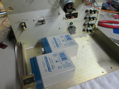
The batteries would not fit without modifications to some of the switching, so it was handy that I decided to forgo the continuity / proximity cue circuit, and turn the speaker terminals into a charging input. The batteries are oriented in a manner that won't interfere with switches and will allow the panel to close. The preference would have been a symmetrical layout to keep the weight distributed, but I consider myself a bit lucky to have been able to fit them within the unit.


The cells are traced out. X marks are made at six points half way along the edges, holes wide enough to accept large zip ties are drilled at these points.


Batteries are tied down tightly with zip ties. In a worst-case scenario the zip ties can always be cut for removal, and replaced for return of the cells.


Everything seems to fit.


The batteries are wired in series (positive pole of one battery to negative of the other) to double the voltage to 12. For an added measure of protection, I decide to add a fuse to the circuit. Holes are drilled into the side wall.


Butt connectors are tied together and connected to the lead coming off the positive terminal of the cell pack. Zip tie is pre-pulled.


This is designed to protect the circuitry (and battery) from a dead short, so a 10-ampere fuse should be low enough to protect, yet high enough to allow active current through. I would have preferred a breaker, but they are about 10 bucks, and this solution was less than a twentieth of that.


Wiring is started. The circuit is simple enough that no bread board or PCB is required, but after a 5 minute brainstorm on how to turn a schematic into reality, a wiring harness is sketched out. From the sketch comes a working model.

It is amazing how thought-out plans get dumbed-down when being executed; upon building the wiring harness I see how moronic it is to have four diodes wired parallel when one would to the trick.


All connections made with butt connectors and ring terminals are done. Since there's no access to a working solder iron at this time, some planned steps are skipped, such as the connection of LEDs. These steps will be returned to.


Looks a bit of a mess, but traces out ok using power supply / multimeter.

Time to test: